
Overview
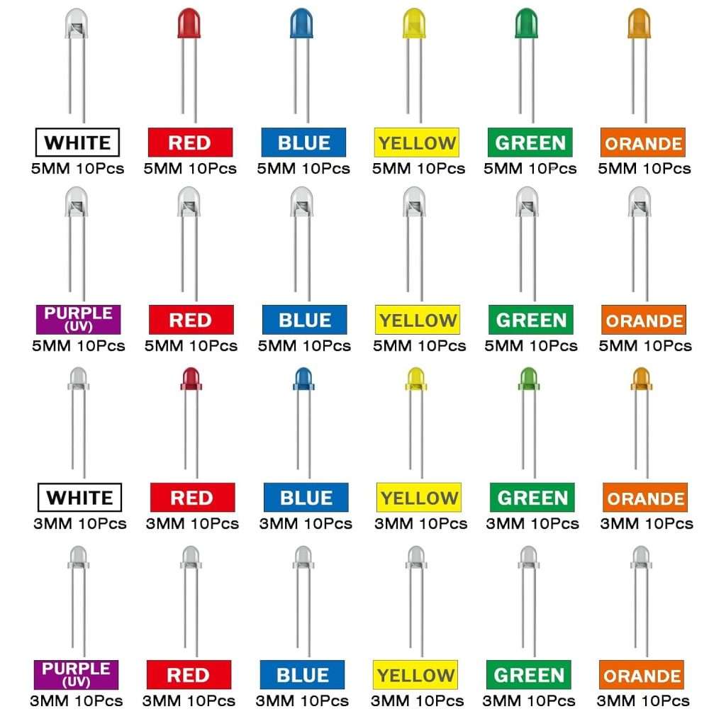
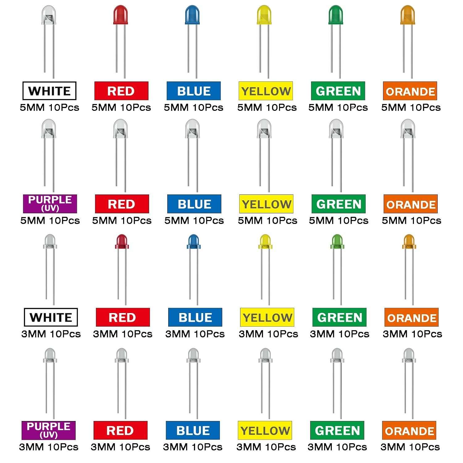
The 240 Pcs 24 Values Multicolor LED Light Emitting Diodes Kit 5MM and 3MM is a general-purpose through-hole LED assortment designed to provide a broad selection of common indicator and lighting LEDs in a compact component kit. Rather than purchasing individual LED colors and package sizes separately, the kit combines 24 different LED variants, covering both 3 mm and 5 mm round through-hole packages, with multiple colors and lens styles.
Available product information identifies the assortment as containing 24 LED types, with the 3 mm and 5 mm versions covering colors such as white, red, blue, yellow, green, orange, transparent-red, transparent-blue, transparent-yellow, transparent-green, transparent-orange, and transparent-purple. A corresponding component-kit listing indicates 10 pieces of each type, resulting in 240 LEDs total.
The LEDs use conventional radial through-hole construction, making them particularly suitable for breadboards, prototype PCBs, educational electronics projects, Arduino-based projects, indicator panels, hobby circuits, and small custom lighting assemblies. The longer and shorter leads provide a convenient visual polarity indication: the long lead is identified as the anode (+), while the short lead is the cathode (-).
One important engineering consideration is that an LED is a current-driven semiconductor device, not simply a component that should be connected directly across a voltage source. The forward-voltage requirement varies substantially with LED color. According to the available product specifications, the listed white, green, clear-green, blue, and clear-blue LEDs are specified around 3.0–3.2 V at 20 mA, while red and clear-red versions are around 2.0–2.2 V, yellow/orange variants around 1.8–2.0 V, and clear-purple around 3.2–3.4 V.
Because individual LED electrical characteristics can vary between manufacturers and batches, these figures should be regarded as the published assortment specifications rather than a substitute for a specific manufacturer’s datasheet.
Technical Specifications
| Specification | Details |
|---|---|
| Product Type | Through-hole LED assortment kit |
| Total Quantity | 240 pieces |
| Number of LED Values | 24 |
| Quantity per Value | Approximately 10 pieces |
| LED Package Sizes | 3 mm and 5 mm |
| Package Shape | Round through-hole LED |
| LED Colors | White, red, blue, yellow, green, orange, purple and transparent variants |
| Lens Variants | Colored and transparent/clear lens styles |
| Lead Type | Radial through-hole leads |
| Typical Lead Length | Long lead approximately 19 mm; short lead approximately 18 mm |
| Polarity Identification | Long lead = anode (+); short lead = cathode (-) |
| Lead Material | Tinned copper pins |
| Encapsulation | Epoxy resin |
| Nominal Maximum/Operating Current Listed | 20 mA |
| Forward Voltage, White/Green/Blue Groups | Approximately 3.0–3.2 V |
| Forward Voltage, Red Group | Approximately 2.0–2.2 V |
| Forward Voltage, Yellow/Orange Group | Approximately 1.8–2.0 V |
| Forward Voltage, Clear Purple | Approximately 3.2–3.4 V |
| Mounting | Through-hole |
| Storage | Assortment organizer/compartment packaging |
| Typical Applications | Indicators, Arduino, breadboards, educational projects, prototypes and DIY lighting |
| Resistor Guide | Included/indicated with the assortment packaging |
| RoHS/Certification Information | Not independently specified in the available product information |
The published specifications consistently identify the kit as a 24-value, 240-piece assortment, although exact manufacturer part numbers, luminous intensity, viewing angle, wavelength, reverse-voltage rating, and detailed binning information are not provided. Consequently, these parameters should not be assumed to be identical across every LED in the kit.
Key Features
1. 24 LED Variants in One Kit
The principal advantage of the assortment is its variety. Instead of maintaining separate inventories of red, green, blue, yellow, white and orange LEDs in different package sizes, the kit consolidates 24 different variants into one collection.
The available component listing identifies 12 variants in the 3 mm size and the corresponding 12 variants in the 5 mm size, with approximately 10 pieces per variant.
This arrangement is useful for engineers and makers who frequently prototype circuits but do not always know in advance which LED color or package size will be required.
2. Both 3 mm and 5 mm Packages
The two most common traditional through-hole LED dimensions are represented.
3 mm LEDs are useful where PCB space is restricted or where a relatively small indicator is desirable. They work well on compact control panels, small development boards and densely populated prototype circuits.
5 mm LEDs, meanwhile, provide a larger visible area and are commonly used for status indicators, front-panel illumination, educational projects and general-purpose visual feedback.
Having both dimensions in one kit avoids the need to redesign a prototype simply because a different physical LED diameter is required.
3. Multiple Electrical Characteristics
LED color is not merely a cosmetic difference. Different semiconductor materials and emission wavelengths result in different forward-voltage characteristics.
The published values illustrate this clearly. Red LEDs are listed around 2.0–2.2 V, while yellow and orange devices are approximately 1.8–2.0 V. Blue, green and white devices are generally higher, around 3.0–3.2 V, with clear-purple listed around 3.2–3.4 V.
This makes the assortment particularly useful for learning practical LED circuit design because the user can observe how different LED types respond to the same supply voltage.
4. Conventional Through-Hole Construction
The LEDs use straightforward radial leads, making them compatible with solderless breadboards and conventional through-hole PCBs.
For beginners, through-hole LEDs are also easier to handle than tiny surface-mount LEDs. Their physical size, visible polarity markings and long leads make them convenient for introductory electronics work.
5. Clearly Identifiable Polarity
The published product description specifies a longer approximately 19 mm lead for the anode and a shorter approximately 18 mm lead for the cathode.
Although users should still verify polarity using the package shape or a meter when necessary, the lead-length difference provides a convenient first-level identification method.
6. Epoxy Encapsulation and Tinned Leads
The available specifications describe an environmental-protection epoxy resin encapsulation and tinned copper leads intended to provide corrosion resistance and good electrical/thermal conductivity.
This is typical construction for general-purpose indicator LEDs and provides a mechanically robust package for breadboard and through-hole assembly work.
7. Convenient Component Organization
A mixed LED assortment becomes significantly more useful when the components can be quickly identified and returned to their appropriate location. The product description emphasizes organized packaging and a resistor color-code guide to simplify identification and use.
For a workshop environment, this is more practical than keeping dozens of loose LEDs in an unorganized container.
Application Scenarios
Arduino and Microcontroller Projects
The kit is particularly suitable for Arduino, ESP32, STM32 and other microcontroller development projects. LEDs can provide visual feedback for GPIO states, communication status, sensor thresholds, user-interface events and system operating modes.
For example, a red LED could indicate an error condition, green could indicate normal operation, while yellow or orange could indicate a warning or intermediate state.
When driven from a microcontroller GPIO, a series current-limiting resistor should normally be used. The resistor value can be estimated using:
R = (VCC − VF) / ILED
For example, with a 5 V supply, a red LED having approximately 2.0 V forward voltage and a desired current of 10 mA would require approximately:
R = (5 − 2.0) / 0.01 = 300 Ω
A nearby standard resistor value such as 330 Ω would therefore be a practical starting point.
Breadboard Prototyping
Through-hole LEDs are particularly convenient on solderless breadboards. A user can quickly assemble an indicator circuit, experiment with different resistor values and compare different LED colors without permanently modifying a PCB.
The 3 mm and 5 mm options also allow the physical appearance of the prototype to be adjusted according to available space.
Educational Electronics
For students learning Ohm’s law, semiconductor devices, polarity, current limiting and digital output control, this kit provides a practical collection of components.
An instructor can demonstrate how changing LED color changes forward voltage, or how changing the resistor changes LED current and brightness.
Indicator Panels
The 5 mm LEDs are well suited to equipment status panels and simple human-machine interfaces. Multiple colors can be assigned to different operating conditions.
The 3 mm variants can be preferable when several indicators must be arranged in a limited area.
DIY Lighting and Hobby Electronics
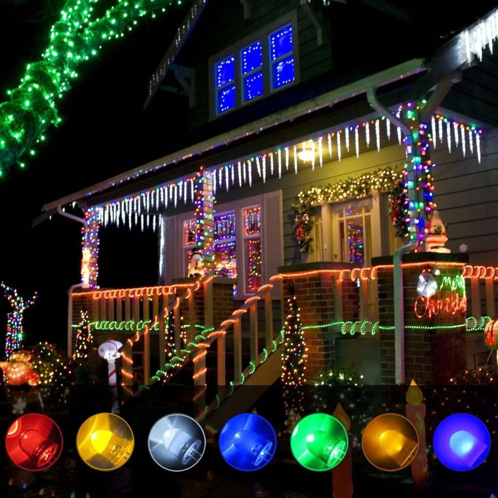
Although these are not high-power illumination LEDs, they are useful for low-power decorative lighting, model electronics, miniature displays, custom control panels and hobby projects where visual indication is more important than high luminous output.
Sensor and Alarm Circuits
The LEDs can also serve as direct visual indicators in comparator, timer, sensor and alarm circuits. For example, a sensor threshold circuit could activate a red LED when a measured parameter exceeds a limit and a green LED when the parameter remains within the desired range.
Competitive Analysis
The LED assortment category can broadly be divided into several approaches: individual LED packs, single-color assortments, large mixed-component kits and dedicated professional LED selections.
| Solution Type | Strengths | Weaknesses |
|---|---|---|
| 240-piece 24-value LED assortment | Broad color/package selection; 3 mm and 5 mm sizes; convenient for general prototyping | Detailed manufacturer-specific electrical data may be limited |
| Single-color LED packs | Consistent color and electrical characteristics | Requires purchasing and storing many separate packs |
| Professional manufacturer LED series | Better traceability, datasheets, luminous-intensity bins and electrical characterization | Usually less convenient and potentially more expensive for casual prototyping |
| Large electronic component kits | Extremely broad component coverage | Individual LED selection may be less comprehensive |
| Small 5 mm LED assortments | Simple and inexpensive; easy to use | Usually lack the 3 mm options and broader color selection |
For professional production designs, a kit such as this should generally be regarded as a prototype and general-purpose component source, rather than as a substitute for a fully characterized production LED.
Commercial LED manufacturers normally provide substantially more detailed parameters, including dominant wavelength, luminous intensity, viewing angle, reverse voltage, thermal characteristics and binning information. Those parameters are important when LEDs must meet consistent optical specifications.
For experimentation, education and low-volume projects, however, the assortment format has a different advantage: breadth and convenience.
Practical Design Considerations
Despite the simplicity of an indicator LED, correct electrical design remains important.
The stated 20 mA value should not automatically be interpreted as the ideal operating current for every application. Lower currents such as 2–10 mA are often sufficient for indicator applications and can reduce power consumption.
The forward voltage also needs to be considered when selecting the current-limiting resistor. A resistor suitable for a red LED at a particular supply voltage will not necessarily produce the same current in a blue or white LED.
For example, assuming a 5 V supply:
| LED Group | Approx. Forward Voltage | Example Current | Approx. Resistor |
|---|---|---|---|
| Red | 2.0 V | 10 mA | 300 Ω |
| Yellow/Orange | 1.9 V | 10 mA | 310 Ω |
| Blue/White | 3.1 V | 10 mA | 190 Ω |
| Clear Purple | 3.3 V | 10 mA | 170 Ω |
These are calculated examples, not guaranteed production values for every LED in the assortment. In practical circuits, a nearby standard resistor value and the actual measured/datasheet forward voltage should be used.
It is also important to recognize that LED brightness is not determined solely by current. Different LED colors and batches can have different luminous efficiencies and optical characteristics. Therefore, visually matching brightness between different colors may require different drive currents.