.webp "ADS1115(9)")

.webp "ADS1115(12)")
-100x100.webp "ADS1115(9)")

-100x100.webp "ADS1115(12)")
ADS1115 Precision ADC Pro Gain Amplifier Module
$1.27
Quick RFQ
ADS1115 Precision ADC Pro Gain Amplifier Module(16 Bit/4 Channel/2.0V to 5.5V)
♦ADS1115 Module Blue
Features
- Resolution: 16 Bits
- Programmable Sample Rate: 8 to 860 Samples/Second
- Power Supply/LogicLevels: 2.0V to 5.5V
- Low Curent Consumption: Continuous Mode: Only 1 50μA Single- Shot Mode: Auto Shut-Down
- Intemal Low-Drift Voltage Reference
- Intemal Oscillator
- Internal PGA: up to x16
- I2C Interface: 4-Pin-Selectable Addresses
- Four Single-Ended or 2 Differential Inputs
- Programmable Comparator
.webp)
Assembly
The board comes with all surface-mount parts pre-soldered. For breadboard use, the included header-strip should be soldered on:
1,Prepare the header strip
Cut the supplied header strip to length and insert it long-pins-down in your breadboard to hold it for soldering.
.webp)
2,Position the breakout board
Place the breakout board on the header pins.
.webp)
3,Solder each pin for a good electrical connection.
.webp)
Wiring
1,Power
First connect VDD and GND. These boards will work with eithera 3.3v or a 5v supply. The diagram below shows connection to the Arduine 5v pin.
.webp)
2,I2C Connections
I2C requiresjust 2 pins to communicate. These can be shared with other I2C devices. For R3 and later Arduinas (induding MEGA and DUE models), connect SDA-> SDA and SCL->SCL.
.webp)
3,I2C “Classic”
For older Arduing boards without dedicated SDA and SCL pins, connect as shown below.
.webp)
4,I2C Addressing
The ADS11x5 chips have a base 7-bit I2C address of 0x48 (1001000) and a clever addressing scheme that allows four different addresses using just one address pin (named ADR for ARdRess). To program the address, connect the address pin as follows:
●0 x 48 (1001000) ADR -> GND
●0 x 49 (1001001) ADR -> VDD
●0 x 4A (1001010)ADR -> SDA
●0 x 4B (1001011)ADR -> SCL
The following diagram shows one board addressed as 0 x 48:
.webp)
5,Multiple Boards
By assigning each board a different address, up to 4 boards can be connected as below:
.webp)
♦ADS1115 Module Purple
Introduction
For microcontrollers without an analog-to-digital converter or when you want a higher-precision ADC, the ADS1115 provides 16-bit precision at 860 samples/second over I2C.The chip can be configured as 4 single-ended input channels, or two differential channels.As a nice bonus, it even includes a programmable gain amplifier, up to x16, to help boost up smaller single/differential signals to the full range. We like this ADC because it can run from 2V to 5V power/logic, can measure a large range of signals and its super easy to use.It is a great general purpose 16 bit converter.
The chip’s fairly small so it comes on a breakout board with ferrites to keep the AVDD and AGND quiet. Interfacing is done via I2C. The address can be changed to one of four options,so you can have up to4 ADS1115’s connected on a single 2-wire I2C bus for 16 single ended inputs.
Parameters
- Wide supply range: 2.0v to 5.5v
- Low current consumption: continuous mode: only 150μa
- Single-shot mode: auto shut-down
- Programmable data rate: 8sps to 860sps
- Internal low-drift voltage reference
- Internal oscillator
- I2c interface: pin-selectable addresses
- Internal pga
- Four single-ended or two differential inputs
- Programmable comparator
| Series | ADS1115 Blue, ADS1115 Purple |
|---|
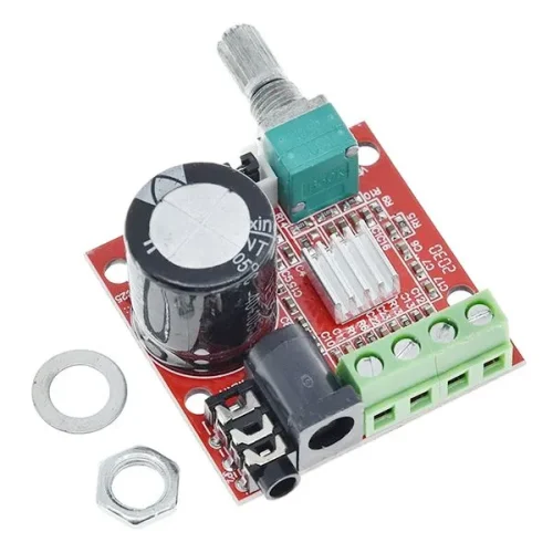
PAM8610 Mini Hi-Fi Audio Stereo Amplifier Module
$1.68 Select options This product has multiple variants. The options may be chosen on the product page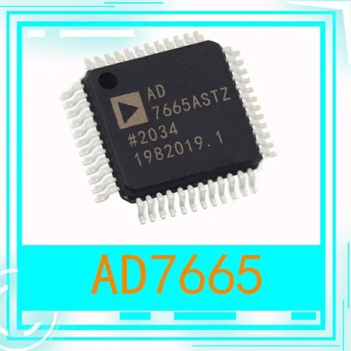
AD7665 IC Chip
$15.78 Select options This product has multiple variants. The options may be chosen on the product page-500x500.webp "BF350-3AA(1)")
BF350-3AA Precision Resistive Strain Gauge
$1.52 – $3.43 Select options This product has multiple variants. The options may be chosen on the product page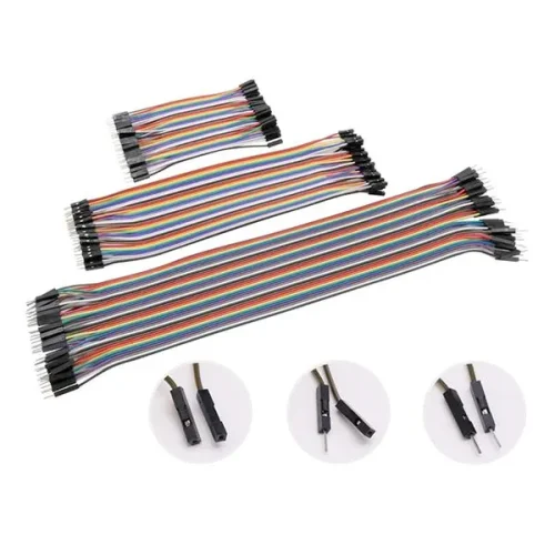
Jumper Wires 40Pin
$1.76 – $2.84 Select options This product has multiple variants. The options may be chosen on the product page
Pro Micro ATmega32U4 5V 16MHz Original Chip Replace ATmega328 For Arduino Pro Mini With 2 Row Pin Header For Leonardo UNO R3
$3.92 – $5.56 Select options This product has multiple variants. The options may be chosen on the product page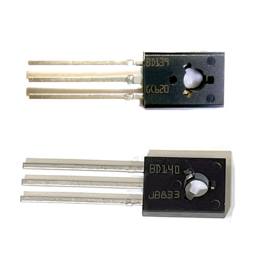
BD139 BD140 Transistors for Audio Power Amplifiers in Complementary Circuits
$4.70 Select options This product has multiple variants. The options may be chosen on the product page
Related products
Buck-boost Low Noise Regulated Charge Pump Module
$0.52 – $1.61 Select options This product has multiple variants. The options may be chosen on the product page
CAR USB Charger Module 6-24V 12V/24V to 5V 3A
$0.53 – $1.09 Select options This product has multiple variants. The options may be chosen on the product page
Step Down Module 300W 20A
$5.54 Select options This product has multiple variants. The options may be chosen on the product page
XL6019 Step Up Power Module
$0.97 Select options This product has multiple variants. The options may be chosen on the product page