-e1713751847613.webp "AT89C2051(1)")
AT89C2051 Electronic Clock Module
$1.63
Quick RFQ
AT89C2051 Electronic Clock Module(Digital 4 Bits/DIY Kit)
Description
Supply voltage : 3V-5.5V
The program of the microcontroller has been copied in, pay attention to the positive and negative poles, do not exceed 5.2V.
Resistors, ceramic capacitors, buttons, and crystal oscillators are not divided into positive and negative poles. The long foot of the buzzer is the positive pole. The chip and base notch direction corresponds to the notch direction on the board. There is a white square mark on one end of the resistance exclusion, which corresponds to the white square mark on the board.
End welding, power supply problems, use DC voltage.
.webp)
Instruction For Use
When you power on the device, it displays the time interface as 12:59. By default, the system activates both alarm clocks. You can set the first alarm clock for 13:01 and the second one for 13:02.
After power-on, short press S2 to switch between the hour and minute time interface and the minute and second time interface, long press the S1 key to enter the system menu setting,there are nine sub-sectionsA, B, C, D, E,F, G, H, 1. menu, short press the S1 submenu to add 1, and finally return to the travel time interface.
A Submenu: To correct hours, press S2 key to add 1 up; after adjustment, short press S1 to save and exit this submenu to enter B submenu.
B Submenu: To correct minutes, press S2 key to add 1 up; after adjustment, short press S1 to save and exit this submenu to enter C submenu.
C Submenu: you can toggle the Hourly Time Chime switch. Its default state is ON (the chime sounds every hour from 8 o’clock to 20 o’clock). Press S2 to switch between ON and OFF (to disable the hourly chime). After making adjustments, press S1 briefly to save the settings and exit this submenu, then enter the D submenu.
D Submenu: you can toggle the switch for the first alarm clock. Its default state is ON (the first alarm clock is enabled). Press S2 to switch between ON and OFF (to disable the first alarm clock).
If set to ON, short press S1 to save and exit this submenu to enter E submenu;
If set to OFF, short press S1 to save and exit to directly enter the G submenu.
E submenu: Set the first alarm clock hour,press S2 toadd 1 up; after adjustment, short press S1 to save and exit this submenu to enterF submenu.
F submenu: Set the minutes of the first alarm clock, press S2 to increase by 1;after adjustment, short press S1 to save and exit this submenu to enter G submenu.
G submenu:you can toggle the switch for the second alarm clock. Its default state is ON (The user has enabled the second alarm clock.). Press S2 to switch between ON and OFF (to disable the second alarm clock).
If set to ON, short press S1 to save and exit this submenu to enter H submenu;
If set to OFF, short press S1 to save and exit to return to the travel time interface directly.
H submenu:Adjust second alarm,Press S2 to increase hour. Save with short S1 press. Exit to I submenu.
I submenu: Set second alarm minute,Press S2 to increase. Save with short S1 press. Exit to J menu.
J Submenu: Adjust the clock speed, press S2 to increase by 1, there are 9 gears in total,the larger the number, the faster the clock runs; after adjustment, short press S1 to save and exit, and enter the travel time interface.
Time and second correction: Short press S2 on the travel time interface to enter the minute and second display interface, long press S2 to reset the second to zero, and then short press S2 twice to check whether the current second is on time.
Components List
| Name | Quantity | Number |
| PCB Board | 1 | / |
| Common cathode digital tube | 1 | DS1 |
| 89C2051 Chip | 1 | U1 |
| 20P Chip holder | 1 | U1 |
| Resister Packs | 1 | PR1 |
| 10uF Electrolytic capacitor | 1 | C1 |
| 8550 Triode | 1 | Q1 |
| 10K Resistor | 2 | R1,R2 |
| Active buzzer | 1 | LS1 |
| 104 Ceramic capacitor | 1 | C4 |
| 30P Ceramic capacitor | 2 | C2,C3 |
| 12M Crystal oscillator | 1 | Y1 |
| 6*6*6 Button | 2 | S1,S2 |
| 2P Terminal | 1 | J1 |
.webp)
.webp)
| Series | AT89C2051 DIY Kit |
|---|
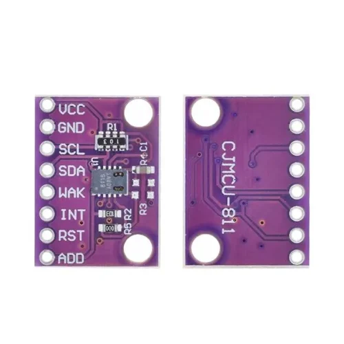
CCS811 Gas Sensor Module
$7.61 Select options This product has multiple variants. The options may be chosen on the product page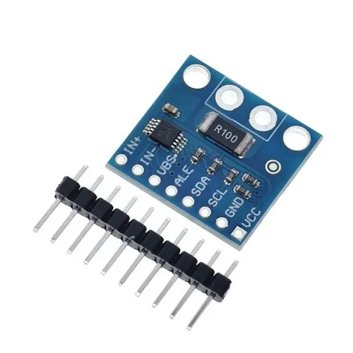
INA226 Bi-directional Current/Power Monitoring Sensor Module
$1.14 Select options This product has multiple variants. The options may be chosen on the product page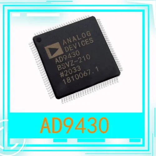
AD9430 IC Chip
$37.54 Select options This product has multiple variants. The options may be chosen on the product page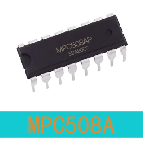
MPC508A IC Chip
$20.93 Select options This product has multiple variants. The options may be chosen on the product page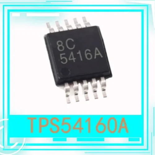
TPS54160A DGQR msop-10 Chipset
$3.63 Select options This product has multiple variants. The options may be chosen on the product page-500x500.webp "PAM8610(3)")
PAM8610 Digital Power Amplifier Board Module
$0.77 Select options This product has multiple variants. The options may be chosen on the product page
Related products

DC-DC Boost Module 0.9-5V To 5V-9V with different output current
$0.51 – $1.95 Select options This product has multiple variants. The options may be chosen on the product page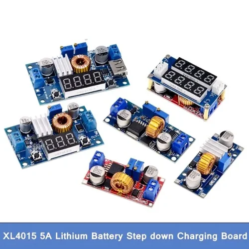
XL4015 Lithium Charger Step Down Module
$0.99 – $3.95 Select options This product has multiple variants. The options may be chosen on the product page
Adjustable DC-DC USB Boost Power Regulator 5V to 24V
$1.31 Select options This product has multiple variants. The options may be chosen on the product page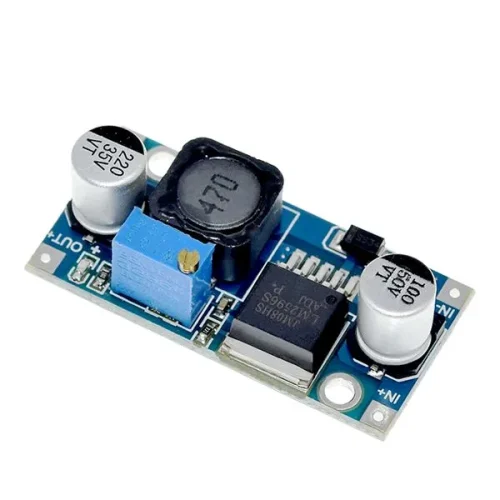
LM2596 DC-DC Step-down Module
$0.65 Select options This product has multiple variants. The options may be chosen on the product page